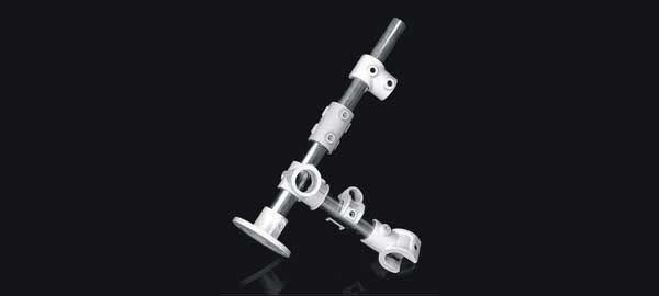
Glass plant and equipments are supported in a rectangular tubular structure.
This tubular structure consisting of galvanized mild steel tubing with cast iron fitting, which are described in this catalogue. This type of structure provides enough flexibility for future modifications and is strong enough to support a glass plant.
S.S Tubing and / or powder coated structure parts can also be supplied on request.
Since there are various terminologies in common uses to determine tube size, the following table is given to compare and relate them to the fitting size reference.
| TUBE INCHES DIAMETER | NOMINAL BORE mm | EXTERNAL DIAMETER mm |
|---|---|---|
| 3/4" | 19 | 21.5 |
| 1" | 25 | 32.5 |
| 1 1/4" | 30 | 41.5 |
| 1 1/2" | 40 | 48.3 |
n the design of tubular structure to support glass process plant and pipeline equipment, a number of basic rules should be followed.
The structure should be stiff and should always be braced back to the nearest building or other stiff feature to give lateral support.
All glass units are built up from a fixed point on which whole weight of the column should be taken. If a total load exceeds the allowable limits, counter balance supports should be used to relieve excessive weight.
All Glass unit and their structures expand at different rate as a result of change in temperature. The unit must, therefore, not be subjected to any vertical restraint above the fixed point. Due to this guide are used which give lateral support without affecting vertical movement of the glass relative to the supporting structure. The distance between guide frames must not exceed 3meters.
The whole weight of a column must be taken up from the fixed point. This normally presents no problem up to DN 300, but with larger columns it may be necessary to take up some of the weight by means of counterbalance supports.
Following structure fittings are available to use with galvanized Iron tubes in order to form a tubular structure of a glass plant. This fittings are made of cast iron and are suitable to the galvanize tubes described as earlier.
These sliding are provided with grub screws to fix it at required position on at galvanized tube.

| DOUBLE BEND | NB | CAT. REF. |
|---|---|---|
| 25 | SDB 25 | |
| 30 | SDB 30 | |
| 40 | SDB 40 | |
| 50 | SDB 50 |

| CROSS | NB | CAT. REF. |
|---|---|---|
| 25 | SX 25 | |
| 30 | SX 30 | |
| 40 | SX 40 | |
| 50 | SX 50 |

| COUPLER | NB | CAT. REF. |
|---|---|---|
| 25 | SCL25 | |
| 30 | SCL25 |

| SUPPORT | NB | CAT. REF. |
|---|---|---|
| 15 | SSPT 15 | |
| 25 | SSPT 25 | |
| 30 | SSPT 30 | |
| 40 | SSPT 40 | |
| 50 | SSPT 50 |

| BASE | NB | CAT. REF. |
|---|---|---|
| 25 | SBS 25 | |
| 30 | SBS 30 | |
| 40 | SBS 40 | |
| 50 | SBS 50 |

| EQUAL BRACKET | NB | CAT. REF. |
|---|---|---|
| 25 | SEBT 25 | |
| 30 | SEBT 30 | |
| 40 | SEBT 40 | |
| 50 | SEBT 50 |
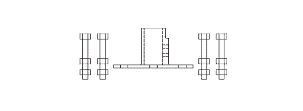
1. Take one cast iron base and four foundation bolts, each with 2 nuts.

2. Fit the bolts in base so that base raised up to 150 mm from head of bolts.
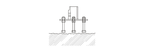
3. Put this assembly on the floor and prepare a rough surface for proper bonding of grounding.
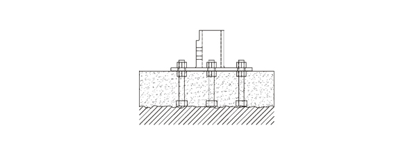
4. Make a concrete block over the bolts of about 200 x 200 mm up to the base of BASE I.e 150 mm High.

5. Prepare separate block for each base instead of making one big common block for all bases.
Structures are designed to support plant and other equipment comprising components exclusively or principally in borosilicate glass 3.3 Because of the special requirements resulting from the use of this material. Mostly these structures consist of steel/galvanized tubing in four different diameters, which are connected using the suitable fittings. As a result, the structures cannot only be dismantled and reassembled whenever required but they can also be modified and added to quite easily.
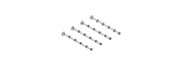
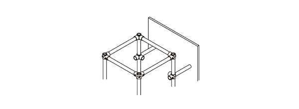
Side the fittings on to the tubes in correct sequence and lightly tighten in approximate position.
Assemble one side frame of the structure by adding the cross tubes between two vertical tubes.

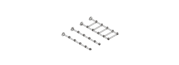
Assemble one side frame of the structure by adding the cross tubes between other two vertical tubes.

Build up the cross tubes to form the ends of the structure.
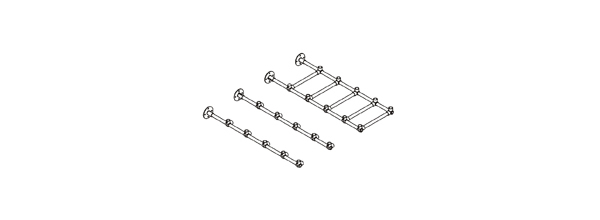
Add the remaining vertical tubes and cross tubes to complete the structure and tighten all the fittings.

Hoist the structure and brace it to some existing rigid feature.
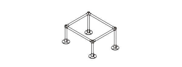
Grout the foundation bolt and fix the structure bases with that.
Adjust bracing to obtain a correct plum in structure.

Adjust the horizontal frames in correct level.

Assemble the support tubes at their positions.