
Capacity : From 5 Kg/Hr to 200 Kg/Hr
Spent Acid (75% H2 SO4) as by product
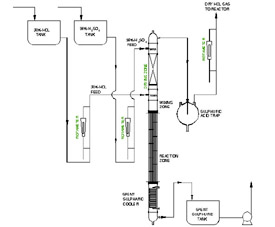
The system consists of
Reaction Zone - Glass
Mixing Zone - Glass
Drying Zone - Glass
Spent Acid Cooling Heat Exchanger - Glass
Sulphuric Acid trap - Glass
98 % H2SO4
30 % HCl
75-78% H2SO4 WITH 2% HCl
Cooling Water 32 Deg C
30% HCl and 98% Sulphuric acid are fed to the Mixing Zone by the metering pump or through Overhead tank depending upon the customer requirement and site height availibility. Both the flow is adjusted by stroke according to the requirement if fed through metering pump. In this case, Feed Rotameter is not required for both HCl and Sulphuric Acid. If both the feed fed to the column from overhead storage tank, Rotameter is to be provided of respective fluid to monitor the flow of fluid.
The HCl and H2SO4 feed are mixed prior to entry into the Reaction zone (Falling Film Tubular Heat Exchanger). The spent Sulphuric acid from the bottom of the Falling Film Tubular Exchanger is cooled in the Heat Exchanger, prior to discharge. The Liquid Cooler uses cooling water for cooling duty.
The HCl gas generated in the Falling Film Tubular Heat Exchanger comes in contact with Conc. H2SO4 in the Drying Zone (Dehydrating packed column). Initial drying of the HCl gas takes place in this section. HCl gas from the top of the Dehydrating column is passed through Sulphuric Acid trap to minimize the moisture content in HCl Gas.
There are no moving parts in the entire system. The utility requirements as well as floor space requirements for the Plant are minimum.
Once all the operating conditions are stabilized and maintained, rate of generation of HCl gas depends only upon rate of Conc. HCl Feed.
All the wetted parts of the system are fabricated from corrosion resistant materials (glass/PTFE) for the process conditions envisaged.
The condensation system at top of column consists of :
Cooling water Condenser
Chilled Water Condenser
Chilled Brine Condenser
Chilled Brine is to be provided to remove the moisture from the HCl gas .If chilled Brine is not available, Sulphuric acid trap is to be provided to remove the moisture from the gas generated. The Product Dry HCl gas is discharged at atmospheric pressure and goes to downstream equipment.
Once all the operating conditions are stabilized and maintained, rate of generation of HCl gas depends only upon rate of conc. HCl Feed.
All the wetted parts of the system are fabricated from corrosion resistant materials (Glass /PTFE) for the process conditions envisaged.