
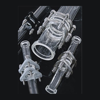
The couplings designed for use with our glass process plant and pipeline components are of major importance from two main points of view.
They must ensure that the bolt load applied to the joint is sufficient to make an effective seal whilst not inducing undue stress in the glass.
They must be totally reliable in all service conditions on the inner walls.
This chapter of the catalogue covers not only the necessary couplings to join glass equipments and pipeline components together but also the couplings needed to join glass to another materials. For glass plants installed in relatively corrosive environments and added advantage is the availability of couplings constructed form various materials including stainless steel and plastic.
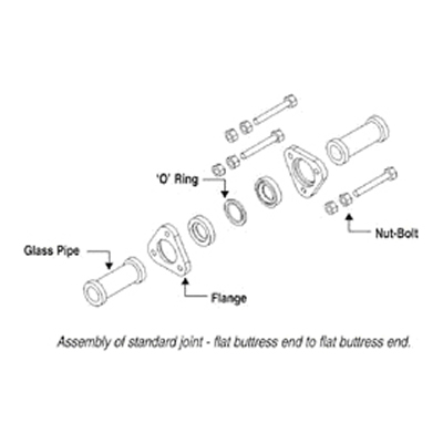
Complete coupling consists of two flanges, two inserts and the appropriate number of nuts, bolts, PTFE 'O' ring.
Generally flanges are made of cast iron powder coated / SS, nuts, bolts, springs.
| DN | Flanges | Inserts | Nuts & blots | Cat. Ref. |
|---|---|---|---|---|
| 25 | 2xCF1 | 2xCN1 | 3x5/16¡±x70 | SCT1 |
| 40 | 2xCF1.5 | 2xCN1.5 | 3x5/16¡±x80 | SCT1.5 |
| 50 | 2xCF2 | 2xCN2 | 3x5/16¡±x90 | SCT2 |
| 80 | 2xCF3 | 2xCN3 | 6x5/16¡±x100 | SCT3 |
| 100 | 2xCF4 | 2xCN4 | 6x5/16¡±x110 | SCT4 |
| 150 | 2xCF6 | 2xCN6 | 6x3/8¡±x120 | SCT6 |
| 225 | 2xCF9 | 2xCN9 | 8x3/8¡±x130 | SCT9 |
| 300 | 2xCF12 | 2xCN12 | 12x3/8¡±x140 | SCT12 |
| 450 | 2xCF450 | 2xCN450 | 12x1/2¡±x200 | SCT18 |
| 600 | 2xCF600 | 2xCN600 | 12x1/2¡±x200 | SCT24 |
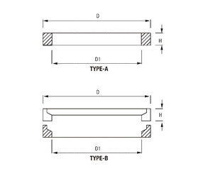
Quick release coupling are used in applications where there is need to open or to close couplings as quickly without using tools. Charging materials to reaction or extraction vessels or replacing measurement indicators are typical examples of this.
Upper flange with slotted bolt -holes, hinged quick release bolts and a lower backing flange, which is fixed on the glass and are separated by means of hinged quick release bolts and wing nuts. Depending upon the frequency of opening.
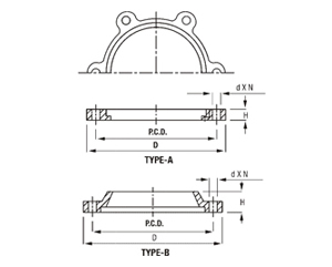
| DN | D | H | P.C.D | D x N | TYPE | Cat. Ref. |
|---|---|---|---|---|---|---|
| 25 | 90 | 10 | 70 | 9 x 3 | A | SCF 1 |
| 40 | 105 | 10 | 86 | 9 x 3 | A | SCF 1.5 |
| 50 | 120 | 11 | 98 | 9 x 3 | A | SCF 2 |
| 80 | 155 | 12 | 133 | 9 x 6 | A | SCF 3 |
| 100 | 200 | 14 | 178 | 9 x 6 | A | SCF 4 |
| 150 | 280 | 15 | 254 | 11 x 6 | A | SCF 6 |
| 225 | 335 | 29 | 310 | 11 x 8 | B | SCF 9 |
| 300 | 420 | 35 | 394 | 11 x 12 | B | SCF 12 |
| 400 | 525 | 22 | 495 | 12 x 12 | A | SCF 16 |
| 450 | 630 | 38 | 585 | 14 x 12 | B | SCF 18 |
| 600 | 745 | 48 | 710 | 14 x 12 | B | SCF 24 |
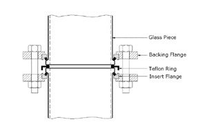
Backing flanges form an internal part of the complete coupling detailed earlier in this chapter. Up to and including DN 450 they are one -piece unit and for DN-600 it is available in two pieces. Backing flanges are used to couple to glass end or to a bellow.
Backing flanges are made of cast iron and are used with inserts.
* Stainless steel (S.S.) flanges can be made on request basis.
Note : H may vary ± 2mm up to DN 150 and ± 3mm from Dn 200 to Dn 600mm
| DN | D | d1 | h | TYPE | CAT. REF |
|---|---|---|---|---|---|
| 25 | 50 | 36 | 8 | A | SCN 1 |
| 40 | 65 | 50 | 8 | A | SCN 1.5 |
| 50 | 79 | 62 | 8 | A | SCN 2 |
| 80 | 110 | 92 | 8 | A | SCN 3 |
| 100 | 146 | 122 | 8 | A | SCN 4 |
| 150 | 197 | 174 | 10 | A | SCN 6 |
| 225 | 275 | 240 | 10 | A | SCN 9 |
| 300 | 359 | 322 | 10 | A | SCN 12 |
| 400 | 474 | 431 | 12 | A | SCN 16 |
| 450 | 555 | 500 | 18 | A | SCN 18 |
Spilt ring type insert are used with backing flanges. This are made of cast iron asbestos rope. Non asbestos PTFE impregnated rope cab be supplied on request. Insert from ruber material can also be supplied on request.
Note : H may vary ± 2mm up to DN 150 and ± 3mm from Dn 200 to Dn 600mm
DN is the nominal size of the coupling.
These flanges are made of cast iron and are supplied with a spilt ring.
Aluminum flanges can also be supplied on request. Please mention Cat.Ref. SCFA for cast iron and SACFA for aluminum flanges.
Adaptor backing flanges are generally supplied undrilled . However , if specified , these can be supplied drilled as per "Table E" ,"Table F" and "ASA 150" standards.
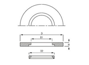
| DN | D | d1 | d2 | h | CAT. REF |
|---|---|---|---|---|---|
| 25 | 115 | 44 | 53 | 7 | SBFA 1 |
| 40 | 150 | 59 | 65 | 9 | SBFA 1.5 |
| 50 | 165 | 70 | 81 | 8 | SBFA 2 |
| 80 | 200 | 104 | 115 | 9 | SBFA 3 |
| 100 | 220 | 133 | 149 | 9 | SBFA 4 |
| 150 | 285 | 189 | 204 | 11 | SBFA 6 |
| 225 | 395 | 261 | 280 | 12 | SBFA 9 |
| Drilled to Table E | Drilled to Table F | Drilled to ASA 150 | ||||||
|---|---|---|---|---|---|---|---|---|
| CAT. REF. | PCD | n x dØ | CAT. REF. | PCD | n x dØ | CAT. REF. | PCD | n x dØ |
| SBFA 1/E | 82 | 4 x 12Ø | SBFA 1/F | 87 | 4 x 16Ø | SBFA 1/A | 79 | 4 x 12Ø |
| SBFA 1.5/E | 98 | 4 x 12Ø | SBFA 1.5/F | 105 | 4 x 16Ø | SBFA 1.5/A | 98 | 4 x 12Ø |
| SBFA 2/E | 114 | 4 x 16Ø | SBFA 2/F | 127 | 4 x 16Ø | SBFA 2/A | 121 | 4 x 16Ø |
| SBFA 3/E | 146 | 4 x 16Ø | SBFA 3/ F | 165 | 8 x 16Ø | SBFA 3/A | 152 | 4 x 16Ø |
| SBFA 4/E | 178 | 8 x 16Ø | SBFA 4/F | 190 | 8 x 16Ø | SBFA 4/A | 190 | 8 x 16Ø |
| SBFA 6/E | 235 | 8 x 19Ø | SBFA 6/F | 260 | 12 x 19Ø | SBFA 6/A | 241 | 8 x 19Ø |
| SBFA 9/E | 324 | 12 x 19Ø | SBFA 9/F | 356 | 12 x 23Ø | SBFA 9/A | 298 | 8 x 19Ø |
Compression rings are used to set and maintain the correct bolts load on standard glass couplings.
Standard compression springs have a corrison resistant coating and are also available in SS.
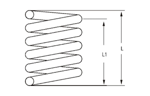
| DN | FREE L | INSTALLED L1 | CAT. REF. |
|---|---|---|---|
| 25 - 100 | 14.5 | 11.0 | SDF 8.5 |
| 150 - 300 | 22.0 | 18.0 | SDF 10.5 |
PTFE 'O' rings are the most widely used gaskets in glass fittings. These are provided with a locking collar, which help to lock the two glass surface correctly. They are manufactured from quality grade of PTFE.
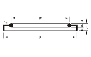
| DN | D | D1 | D | l | CAT. REF. |
|---|---|---|---|---|---|
| 25 | 115 | 43 | 51 | 10 | STR 1 |
| 40 | 150 | 58 | 66 | 10 | STR 1.5 |
| 50 | 165 | 70 | 81 | 12 | STR 2 |
| 80 | 200 | 101 | 112 | 12 | STR 3 |
| 100 | 220 | 134 | 148 | 12 | STR 4 |
| 150 | 285 | 186 | 196 | 15 | STR 6 |
| 225 | 395 | 260 | 282 | 15 | STR 9 |
| 300 | 342 | 318 | 4 | 7 | STR 12 |
| 450 | 537 | 490 | 6 | 7 | STR 18 |
| DN | CAT. REF. |
|---|---|
| 25 | STMP 1 |
| 40 | STMP 1.5 |
| 50 | STMP 2 |
| 80 | STMP 3 |
| 100 | STMP 4 |
| 150 | STMP 6 |
| 225 | STMP 9 |
| 300 | STMP 12 |
| 450 | STMP 18 |
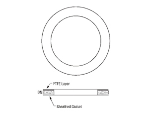
These gaskets take form of a PTFE sheath fitted over a compressed asbestos fiber gaskets. When using this type of gasket, a higher bolting force is required for DN 450 and above.
Please consult our Technical Department for further information.
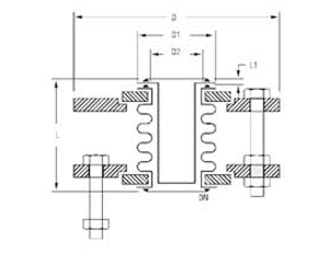
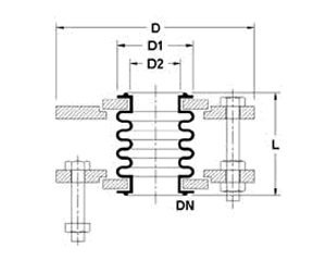
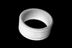
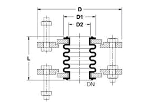
PTFE bellows are an important aid in the construction of glass plant and pipeline.
They can be used to compensate for different thermal movement between glass and associated equipment, absorb vibrations from associated equipment or foundations. In particular, bellows can be used for connecting glass to other materials. When bellows are used, the support and restraint of the glass should be such that the force resulting from pressure/vacuum in the pipeline and forces resulting from Pressure /vacuum in the pipeline and forces resulting from movement of the bellows do not result in undue stresses in the glass. The maximum operating temperature for PTFE bellows is 180°C. Bellows DN 80 and above should not be used under vacuum.
| DN | CAT. REF. | DN | CAT. REF. | DN |
|---|---|---|---|---|
| 15 | -1/+4 | -1/+3 | -1/+1.5 | |
| 25 | -1/+4 | -1/+3 | -1/+1.5 | |
| 40 | -1/+4 | -1/+3 | -1/+1.5 | |
| 50 | -1/+4 | -1/+2 | -1/+1 | Unpressurised |
| 80 | -1/+3 | -1/+2 | -1/+1 | |
| 100 | -1/+2 | -1/+2 | -1/+1 | |
| 150 | -1/+2 | -1/+1.5 | -1/+0,7 | |
| 200 | -1/+1 | -1/+1 | -1/+0,5 |
Permissible operating conditions for SBFN bellows
Permissible operating pressure (bar g)
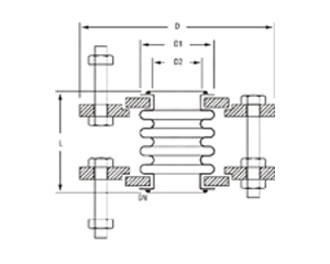
GLASS TO GLASS (LINE BELLOW)
| DN | d | d1 | d2 | l | CAT. REF. |
|---|---|---|---|---|---|
| 25 | 90 | 41 | 31 | 60 | SFBN 1 |
| 40 | 105 | 56 | 43 | 60 | SFBN 1.5 |
| 50 | 121 | 69 | 55 | 60 | SFBN 2 |
| 80 | 155 | 98 | 82 | 65 | SFBN 3 |
| 100 | 200 | 132 | 111 | 65 | SFBN 4 |
| 150 | 274 | 184 | 162 | 65 | SFBN 6 |
| 225 | 340 | 258 | 230 | 65 | SFBN 9 |
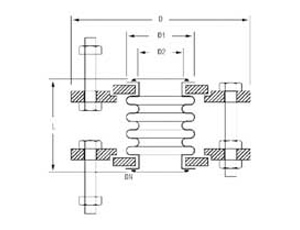
OTHER MATERIALS (LINE BELLOW)
| DN | d | d1 | d2 | l | CAT. REF. |
|---|---|---|---|---|---|
| 25 | 90 | 41 | 31 | 60 | SFBF 1 |
| 40 | 105 | 56 | 43 | 60 | SFBF 1.5 |
| 50 | 121 | 69 | 55 | 60 | SFBF 2 |
| 80 | 155 | 98 | 82 | 65 | SFBF 3 |
| 100 | 200 | 132 | 111 | 65 | SFBF 4 |
| 150 | 274 | 184 | 162 | 65 | SFBF 6 |
| 225 | 340 | 258 | 230 | 65 | SFBF 9 |
GLASS TO GLASS (VACUUM BELLOW)
| DN | d | d1 | d2 | l | l1 | CAT. REF. |
|---|---|---|---|---|---|---|
| 80 | 155 | 98 | 82 | 70 | 5 | SVBN 3 |
| 100 | 200 | 132 | 111 | 70 | 5 | SVBN 4 |
| 150 | 274 | 184 | 162 | 70 | 5 | SVBN 6 |
| 225 | 340 | 258 | 230 | 70 | 5 | SVBN 9 |
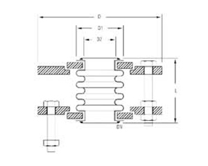
GLASS TO OTHER MATERIALS (VACUUM BELLOW)
| DN | d | d1 | d2 | l | l1 | CAT. REF. |
|---|---|---|---|---|---|---|
| 80 | 155 | 98 | 82 | 70 | 5 | SVBF 3 |
| 100 | 200 | 132 | 111 | 70 | 5 | SVBF 4 |
| 150 | 274 | 184 | 162 | 70 | 5 | SVBF 6 |
| 225 | 350 | 258 | 230 | 70 | 5 | SVBF 9 |
| 300 | 425 | 340 | 308 | 70 | 5 | SVBF 12 |
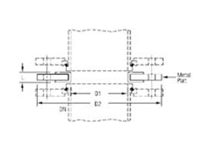
Bellows can be supplied with undrilled adaptor flanges. However , if specified , these can be supplied drilled as per "Table E", "Table F" and "ASA 150" standards.
Tolerances for above bellows in length is ±3mm and diameter as per glass buttress.
| DN | dn1 | dn2 | l | CAT. REF. |
|---|---|---|---|---|
| 25 | 25 | 60 | 10 | SEMP 1 |
| 40 | 37 | 80 | 10 | SEMP 1.5 |
| 50 | 50 | 100 | 10 | SEMP 2 |
| 80 | 75 | 120 | 12 | SEMP 3 |
| 100 | 100 | 155 | 12 | SEMP 4 |
| 150 | 150 | 210 | 12 | SEMP 6 |
| 225 | 200 | 260 | 15 | SEMP 9 |
These components are used as interface spacers when connecting glass flat buttress end components to other process plant and pipeline equipment and glass - lined reaction vessels. A combination of steel, rubber and PTFE provide an ideal sealing surface with only PTFE coming into contact with the process fluids to maintain resistance to corrosion.
PTFE bellows are an important aid in the construction of glass plant and pipeline. They can be used to compensate for different thermal movement between glass and associated equipment, absorb vibrations from associated equipment or foundations. In particular, bellows can be used for connecting glass to other materials. When bellows are used, the support and restraint of the glass should be such that the force resulting from pressure/vacuum in the pipeline and forces resulting from Pressure/vacuum in the pipeline and forces resulting from movement of the bellows do not result in undue stresses in the glass. If any doubt, please consult our Technical Department.
All bellows are delivered complete with an appropriate flange assembly as detailed in the diagram and tables. It is essential that the limiting screws are not removed.
The maximum operating temperature for PTFE bellows is 200¡ÆC. Bellows ON 80 and above should not be used under vacuum. For such application we recommend the use of vacuum bellows as detailed on the following page.
| DN | La | lb | Max. operating pressure up to 100¡Æ C (bar.g) | CAT. REF. |
|---|---|---|---|---|
| 25 | 45 | 60 | 3 | SFBN 1 |
| 40 | 50 | 60 | 3 | SFBN 1.5 |
| 50 | 50 | 60 | 2 | SFBN 2 |
| 80 | 65 | 65 | 2 | SFBN 3 |
| 100 | 70 | 65 | 2 | SFBN 4 |
| 150 | 70 | 65 | 1.5 | SFBN 6 |
| 225 | 70 | 70 | 1 | SFBN 9 |
| 300 | 70 | 70 | 0.7 | SFBN 12 |
LA = As per international standards.
LB = As per our standards.
Tolerance ¡¾ 3mm
| DN | d | La | lb | Max. operating pressure up to 100¡Æ C (bar.g) | CAT. REF. |
|---|---|---|---|---|---|
| 25 | 115 | 45 | 60 | 3 | SFBF 1 |
| 40 | 150 | 50 | 60 | 3 | SFBF 1.5 |
| 50 | 165 | 50 | 60 | 2 | SFBF 2 |
| 80 | 200 | 65 | 65 | 2 | SFBF 3 |
| 100 | 220 | 70 | 65 | 2 | SFBF 4 |
| 150 | 285 | 70 | 65 | 1.5 | SFBF 6 |
| 225 | 395 | 70 | 70 | 1 | SFBF 9 |
| 300 | 480 | 70 | 70 | 0.7 | SFBF 12 |
LA = As per international standards.
LB = As per our standards.
Tolerance ¡¾ 3mm
The adaptor flange in this assembly is drilled to suit mating flanges as per "Table E", "Table F", "Table D","ASA 150", if specified.
Bellows can be supplied with undrilled adaptor flanges.