
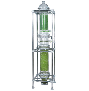
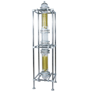
Column components are widely used in chemicals, pharmaceutical and allied industries together with other applications e.g. food and drink production, dye works and electroplating. This is because of the special properties of borosilicate glass 3.3 and PTFE together with special materials that are used in some instances for internals, plus the fact that borosilicate glass 3.3 is an approved and proven material of construction for pressure vessels.
With almost universal resistance to corrosion, a long service life is guaranteed and maintenance is kept to a minimum.
Their transparency permits constant visual monitoring of the process at all times.
Being inert, the risk of contamination is negligible.
Smooth surface allow easy cleaning and sterilization and prevent the build-up of solids on the inner walls.
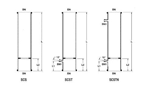
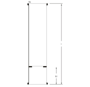
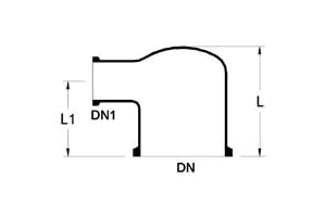
All column sections are supplied complete with support. The packing must be ordered separately.
On special request. A column sections can be supplied without the packing support. Column sections and pipe sections may be used for the construction of columns of all.
| DN | DN1 | l | l1 | l2 | CAT. REF. SCS / SCST / SCSTN |
|---|---|---|---|---|---|
| 80 | 25 | 1000 | 125 | 100 | 3/100 |
| 100 | 25 | 1000 | 125 | 100 | 4/1000 |
| 150 | 25 | 1000 | 125 | 100 | 6/1000 |
| 225 | 25 | 1000 | 125 | 100 | 9/1000 |
| 225 | 25 | 1500 | 150 | 125 | 9/1000 |
| 300 | 25 | 1000 | 150 | 125 | 12/1000 |
| 300 | 25 | 1500 | 150 | 125 | 12/1000 |
| 400 | 25 | 1000 | 200 | 150 | 16/1000 |
| 400 | 25 | 1500 | 200 | 150 | 16/1000 |
| 450 | 25 | 1000 | 200 | 150 | 18/1000 |
| 450 | 25 | 1500 | 200 | 150 | 18/1000 |
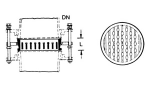
Two types of packing supports Type A or Type B. Type A are made of fused glass rods and Type B (heavy duty) are made of glass plates vertically arranged and tied with PTFE tie rods.
Standard packing supports for columns DN 80 to DN 300 are manufactured from borosilicate glass. From DN 400 and above, a combination of glass and PTFE is used for their construction, thus maintaining maximum resistance to corrosion.
| DN | l | MAXIMUM LOAD (Kg) | MAXIMUM PACKING SIZE (mm) | TYPE | CAT. REF. |
|---|---|---|---|---|---|
| 80 | 20 | 10 | 12 | A | SLB 3 |
| 100 | 20 | 15 | 15 | A | SLB 4 |
| 150 | 30 | 30 | 25 | A | SLB 6 |
| 225 | 30 | 50 | 25 | A | SLB 9 |
| 300 | 30 | 75 | 25 | A | SLB 12 |
| 400 | 70 | 150 | 25 | B | SLB 16 |
| 450 | 70 | 200 | 25 | B | SLB 18 |
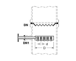
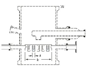
If free cross-section obtained with the combination of column section and packing support are not large enough, then an alternative is to be used with pipe sections in combination with fixed support plate.
Each item comprises glass support plate, screwed rod with nuts, flat washers.
| DN | l | MAXIMUM LOAD (Kg) | CAT. REF. |
|---|---|---|---|
| 80 | 25 | 10 | SLBE 3 |
| 100 | 25 | 15 | SLBE 4 |
| 150 | 50 | 30 | SLBE 6 |
| 225 | 50 | 50 | SLBE 9 |
Rasching rings up to 25mm are made of neutral glass. 40mm and 50mm Rasching Rings are available in borosilicate glass.
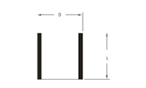
| D X L | WALL THICKNESS (T) | BULK DENSITY (Kg/Ltr.) | SPECIFIC SURFACE (M²/M³) | CAT. REF. |
|---|---|---|---|---|
| 8 X 8 | 1.0 | 0.60 | 500 | SFC 8 |
| 12 X 12 | 1.0 | 0.50 | 400 | SFC 12 |
| 15 X 15 | 1.6 | 0.75 | 300 | SFC 15 |
| 20 X 20 | 1.1 | 0.45 | 280 | SFC 20 |
| 25 X 25 | 2.0 | 0.27 | 200 | SFC 25 |
| 30 X 30 | 2.0 | 0.40 | 176 | SFC 30 |
| 40 X 40 | 1.75 | 0.27 | 160 | SFC 40 |
PACKING SIZE (mm)
| COLUMN SECTION SIZE | Vol LITER | SFC 8 | SFC 12 | SFC 15 | SFC 20 | SFC 25 | SFC 30 | SFC 40 | SFC 50 |
|---|---|---|---|---|---|---|---|---|---|
| SCS 3/1000 | 4.4 | 2.6 | 2.2 | 3.3 | 2.0 | 1.2 | 1.8 | 1.2 | 1.1 |
| SCS 4/1000 | 7.6 | 4.6 | 3.8 | 5.7 | 3.4 | 2.1 | 3.0 | 2.1 | 1.9 |
| SCS 6/1000 | 15.5 | 9.3 | 7.8 | 11.6 | 7.0 | 4.2 | 6.2 | 4.2 | 3.9 |
| SCS 9/1000 | 31.8 | 19.1 | 15.9 | 23.9 | 14.3 | 8.6 | 12.7 | 8.6 | 8.0 |
| SCS 12/1000 | 61.9 | 37.1 | 31.0 | 46.4 | 27.9 | 16.7 | 24.8 | 16.7 | 15.5 |
| SCS 16/1000 | 110 | 66.0 | 55.0 | 82.5 | 49.5 | 29.7 | 44.0 | 29.7 | 27.5 |
| SCS 18/1000 | 145 | 87.0 | 72.5 | 108.8 | 65.3 | 39.2 | 58.0 | 39.2 | 36.3 |
| SCS 24/1000 | 255 | 153.0 | 127.5 | 191.3 | 114.8 | 68.9 | 102.0 | 68.9 | 63.8 |
Notes of use of column packing
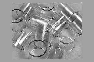
Due to their low bulk density, glass rasching rings are particularly suitable for packing glass columns.
Generally the ratio of column diameter to packing diameter should not be less than 8:1.
When using smaller packing size, a small layer of larger packing should be used on packing support, to prevent the smaller packing falling through.
In vacuum application and applications involving high vapur velocities, packing.
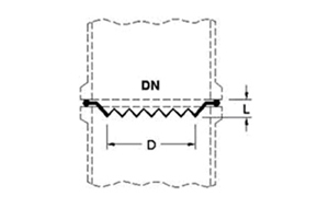
PTFE re-distributors are installed in the same way as gaskets between two flat buttress end faces and therefore when using them, no gasket is required.
| DN1 | d | l | Cat. Ref. |
|---|---|---|---|
| 40 | 28 | 10 | STL 1.5 |
| 50 | 35 | 10 | STL 2 |
| 80 | 55 | 10 | STL 3 |
| 100 | 70 | 15 | STL 4 |
| 150 | 105 | 15 | STL 6 |
| 225 | 140 | 15 | STL 9 |
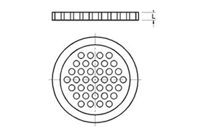
Packing retainers are installed above packed column section to prevent any carry-over of column packing. They are installed in the same way as gaskets between two flat buttress end faces and therefore no gasket is required. Packing retainers are manufactured from PTFE for maximum resistance to corrosion. They cannot be used as packing supports.
| DN1 | l | Free cross-section (%) | Cat. Ref. |
|---|---|---|---|
| 80 | 7 | 80 | SCPC 3 |
| 100 | 7 | 90 | SCPC 4 |
| 150 | 7 | 90 | SCPC 6 |
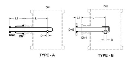
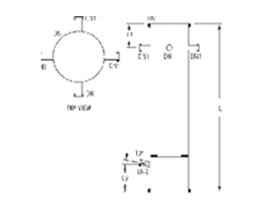
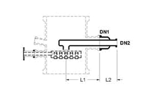
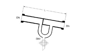
Column feed pipes are designed for application in which there is need to introduce the process liquid at a single point. They are usually installed SPTU unequal tee piece (see Chapter 2 of this catalogue - Pipeline Components) and used as a distribution tube, which directs the fluid down onto center of column packing.
Column feed pipes are available for 80 DN to 600 DN column. Two types of column feed pipes are available as under :
(1) Dip pipe type (Type-A)
(2) Plate type (Type-B)
| DN | DN1 | DN2 | d | l | l1 | Cat. Ref. |
|---|---|---|---|---|---|---|
| 80 | 40 | 25 | 13 | 100 | 115 | SFP 3 |
| 100 | 40 | 25 | 13 | 125 | 115 | SFP 4 |
| 150 | 40 | 25 | 13 | 150 | 115 | SFP 6 |
| 225 | 40 | 25 | 13 | 185 | 115 | SFP 9 |
| 300 | 40 | 25 | 13 | 230 | 115 | SFP 12 |
| 450 | 80 | 40 | 25 | 320 | 150 | SFP 18 |
Spray feed sections are provided with circular tube having holes at bottom
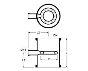
| DN | DN1 | l | l1 | l2 | DIA OF HOLE x NO. OF HOLES | Cat. Ref. |
|---|---|---|---|---|---|---|
| 80 | 25 | 200 | 100 | 100 | 2 x 20 | SFR 3 |
| 100 | 25 | 250 | 125 | 110 | 2 x 20 | SFR 4 |
| 150 | 25 | 250 | 125 | 150 | 2 x 27 | SFR 6 |
| 225 | 25 | 250 | 125 | 170 | 2 x 27 | SFR 9 |
Like column feed pipes, spray feed pipes are usually installed via a SPTU unequal tee piece. Spray feed pipes sections are provided with oval tube having holes at bottom.
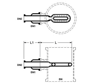
| DN | DN1 | l | l1 | l2 | DIA OF HOLE x NO. OF HOLES | Cat. Ref. |
|---|---|---|---|---|---|---|
| 150 | 80 | 25 | 225 | 125 | 2 x 27 | SFD 6 |
| 225 | 100 | 25 | 325 | 150 | 2 x 27 | FSD 9 |
| 300 | 150 | 25 | 400 | 200 | 3 x 30 | FSD 12 |
| 450 | 150 | 50 | 500 | 200 | 3 x 40 | SFD 18 |
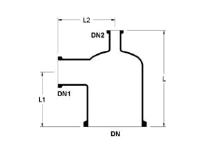
In column feed sparger holes are provided at three sides of pipe.
| DN | DN1 | l | l1 | l2 | DIA OF HOLE x NO. OF HOLES | Cat. Ref. |
|---|---|---|---|---|---|---|
| 80 | 25 | 25 | 125 | 100 | 2 x 21 No. | SSPG 3 |
| 100 | 25 | 25 | 150 | 100 | 2 x 21 No. | SSPG 4 |
| 150 | 40 | 25 | 200 | 100 | 2 x 27 No. | SSPG 6 |
| 225 | 40 | 25 | 275 | 100 | 2 x 27 No. | SSPG 9 |
| 300 | 40 | 25 | 350 | 100 | 3 x 30 No. | SSPG 12 |
| 450 | 40 | 25 | 500 | 100 | 3 x 39 No. | SSPG 18 |
| DN | DN1 | Dn2 | l | l1 | l2 | Cat. Ref. |
|---|---|---|---|---|---|---|
| 80 | 25 | 25 | 180 | 90 | 95 | SCA 3/1/1 |
| 80 | 40 | 25 | 180 | 90 | 110 | SCA 3/1.5/1 |
| 100 | 25 | 25 | 205 | 100 | 110 | SCA 4/1/1 |
| 100 | 40 | 25 | 205 | 100 | 120 | SCA 4/1.5/1 |
| 100 | 40 | 40 | 205 | 100 | 120 | SCA 4/1.5/1.5 |
| 100 | 50 | 25 | 230 | 125 | 125 | SCA 4/2/1 |
| 100 | 50 | 40 | 230 | 125 | 125 | SCA 4/2/1.5 |
| 100 | 100 | 40 | 300 | 150 | 205 | SCA 4/4/1.5 |
| 150 | 40 | 25 | 240 | 125 | 145 | SCA 6/1.5/1 |
| 150 | 50 | 25 | 240 | 125 | 150 | SCA 6/2/1 |
| 150 | 80 | 25 | 255 | 125 | 165 | SCA 6/3/1 |
| 150 | 100 | 25 | 305 | 150 | 205 | SCA 6/4/1 |
| 150 | 40 | 40 | 240 | 125 | 145 | SCA 6/1.5/1.5 |
| 150 | 50 | 40 | 240 | 125 | 150 | SCA 6/2/1.5 |
| 150 | 40 | 50 | 255 | 125 | 145 | SCA 6/1.5/2 |
| 150 | 50 | 50 | 255 | 125 | 150 | SCA 6/2/2 |
| 225 | 40 | 25 | 330 | 150 | 185 | SCA 9/1.5/1 |
| 225 | 50 | 25 | 330 | 150 | 190 | SCA 9/2/1 |
| 225 | 40 | 40 | 330 | 150 | 185 | SCA 9/1.5/1.5 |
| 225 | 50 | 40 | 330 | 150 | 190 | SCA 9/2/1.5 |
| 225 | 80 | 40 | 405 | 230 | 205 | SCA 9/3/1.5 |
| 225 | 100 | 40 | 405 | 230 | 240 | SCA 9/4/1 |
| 225 | 150 | 40 | 405 | 230 | 265 | SCA 9/6/1.5 |
| 225 | 50 | 50 | 355 | 150 | 190 | SCA 9/2/2 |
| 300 | 40 | 25 | 380 | 190 | 220 | SCA 12/1.5/1 |
| 300 | 40 | 40 | 380 | 190 | 220 | SCA 12/1.5/1.5 |
| 300 | 50 | 40 | 380 | 190 | 230 | SCA 12/2/1.5 |
| 300 | 100 | 40 | 430 | 230 | 280 | SCA 12/4/1.5 |
| 300 | 150 | 40 | 430 | 230 | 305 | SCA 12/6/1.5 |
| 300 | 50 | 50 | 405 | 190 | 230 | SCA 12/2/2 |
| 300 | 80 | 40 | 430 | 230 | 240 | SCA 12/3/1.5 |
| 300 | 80 | 50 | 430 | 230 | 240 | SCA 12/3/2 |
| 300 | 100 | 50 | 430 | 230 | 280 | SCA 12/4/2 |
| 300 | 150 | 50 | 430 | 230 | 305 | SCA 12/6/2 |
| 300 | 100 | 100 | 430 | 230 | 275 | SCA 12/4/4 |
| 450 | 50 | 25 | 450 | 275 | 300 | SCA 18/2/1 |
| 450 | 150 | 50 | 550 | 300 | 380 | SCA 18/6/2 |
| 450 | 225 | 50 | 760 | 380 | 405 | SCA 18/9/2 |
| 600 | 150 | 50 | 660 | 300 | 450 | SCA 24/6/2 |
| 600 | 225 | 50 | 700 | 350 | 470 | SCA 24/9/2 |
| 600 | 300 | 100 | 800 | 400 | 525 | SCA 24/12/4 |
| DN | DN1 | l | l1 | l2 | Cat. Ref. |
|---|---|---|---|---|---|
| 150 | 40 | 155 | 110 | 165 | SFH 6/1.5 |
| 225 | 40 | 165 | 120 | 200 | SFH 9/1.5 |
| 300 | 40 | 190 | 140 | 240 | SFH 12/1.5 |
| 450 | 40 | 285 | 175 | 300 | SFH 18/1.5 |
These special column sections are designed specifically for use with type liquid distribution trays (SFVE). They are supplied complete with optional thermometer branch. (See Cat. Ref. SCSTV for thermometer branch in column section.) Column is supplied with 3 sides holding a liquid distribution tray on top if the column at required distance.
| DN | DN1 | l | l1 | l2 | DIA OF HOLE X NO. OF HOLES | Cat. Ref. |
|---|---|---|---|---|---|---|
| 80 | 25 | 25 | 125 | 100 | 2 x 21 No. | SSPG 3 |
| 100 | 25 | 25 | 150 | 100 | 2 x 21 No. | SSPG 4 |
| 150 | 40 | 25 | 200 | 100 | 2 x 27 No. | SSPG 6 |
| 225 | 40 | 25 | 275 | 100 | 2 x 27 No. | SSPG 9 |
| 300 | 40 | 25 | 350 | 100 | 3 x 30 No. | SSPG 12 |
| 450 | 40 | 25 | 500 | 100 | 3 x 39 No. | SSPG 18 |
When used below a PTFE re-distributor, these glass/PTFE distribution trays ensure return of the liquid from the edge of the column and optimum re-distribution. They are installed in type SCSV or SCSTV column sections.
The complete item comprises the tray, support fingers and coupling and gasket to fix them into position.
| DN1 | DN1 | d | d1 | d | Numbered | Cat. Ref. |
|---|---|---|---|---|---|---|
| 225 | 40 | 165 | 140 | 18 | 9 | SFV 9 |
| 300 | 40 | 230 | 200 | 18 | 19 | SFV 12 |
| 450 | 40 | 345 | 315 | 28 | 19 | SFV 18 |
These glass/PTFE distribution trays together with type SFVP inlet feed pipes detailed below are installed via type SFVZ feed sections. They provide an even initial distribution over the column cross-section. The complete item comprises the trays, support fingers and coupling and gaskets to fix them into position.
| DN1 | d | d1 | d | Numbered | Cat. Ref. |
|---|---|---|---|---|---|
| 225 | 165 | 140 | 18 | 8 | SFV 9 |
| 300 | 230 | 200 | 18 | 18 | SFV 12 |
| 450 | 345 | 315 | 28 | 18 | SFV 18 |
These feed pipes are designed specifically for use with the distribution trays.
| DN1 | DN1 | DN2 | l1 | l2 | Cat. Ref. |
|---|---|---|---|---|---|
| 225 | 80 | 25 | 210 | 150 | SFVP 9 |
| 300 | 80 | 25 | 240 | 150 | SFVP 12 |
| 450 | 80 | 40 | 320 | 150 | SFVP 18 |
| 600 | 150 | 50 | 450 | 200 | SFVP 24 |
Distribution plates for liquid feed together with inlet feed pipes, are installed via these special feed sections. They are basically unequal tee pieces with three additional branches for installing the distribution plates and a branch for a thermometer.
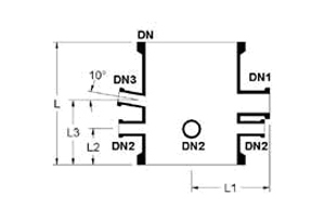
| DN | DN1 | DN2 | dn3 | l | L1 | L2 | l3 | l4 | Cat. Ref. |
|---|---|---|---|---|---|---|---|---|---|
| 225 | 80 | 25 | 25 | 300 | 210 | 110 | 150 | 150 | SFVZ 9 |
| 300 | 80 | 25 | 25 | 400 | 240 | 160 | 210 | 200 | SFVZ 12 |
| 450 | 80 | 40 | 25 | 400 | 320 | 135 | 210 | 200 | SFVZ 18 |
In these units, the reflux is adjusted by means of a valve on the outlet connection. When the valve is fully opened the divider is set to total distillate off-take, Since the reflux pipe is higher than the outlet connection, by regulating the valve, the reflux ratio can be continuous adjusted up to total.
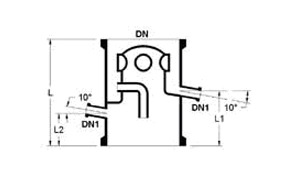
| DN | DN1 | l | L1 | L2 | Cat. Ref. |
|---|---|---|---|---|---|
| 80 | 25 | 190 | 115 | 82 | SRDA 3 |
| 100 | 25 | 255 | 145 | 95 | SRDA 4 |
| 150 | 25 | 255 | 145 | 100 | SRDA 6 |
| 225 | 25 | 380 | 165 | 115 | SRDA 9 |
| 300 | 25 | 380 | 165 | 110 | SRDA 12 |
| MINIMUM SPACE CROSS-SECTION FOR VAPOURS (cm2) | MAXIMUM DISTILLATE VOLUME IN RELATION TO WATER AT 20°C (l/h) (cm2) | Cat. Ref. |
|---|---|---|
| 10 | 300 | SRDA 3 |
| 20 | 475 | SRDA 4 |
| 40 | 700 | SRDA 6 |
| 150 | 900 | SRDA 9 |
| 170 | 1100 | SRDA 12 |
| 670 | 1500 | SRDA 18 |
Liquid seals are fitted on the off-take branch of reflux separators to prevent vapours passing directly to the after-cooler and receivers.
| DN | DN1 | l | Cat. Ref. |
|---|---|---|---|
| 80 | 25 | 160 | SLS 1 |
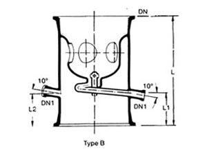
In application where there is need for the reflux to be at a fixed value, then it is advisable to fit an electro-magnetically or pneumatically operated reflux separators in conjunction with timer. Automatically controlled reflux separators are detailed below.
This type of reflux separator uses a swinging funnel mechanism. The funnel, which has a soft iron core sealed into it, is operated magnetically from outside the column so that the condensate can be removed from the column and reflux returned to the column in correct ratio. Activation of the electro-magnet moves the funnel into the off-take position. The electro-magnet (shown dotted) and timer should be ordered separately. Main hole (DN2) is provided for SRHM 9 and above sizes.
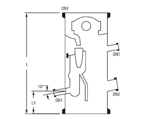
| DN | DN1 | DN2 | l | l1 | Cat. Ref. |
|---|---|---|---|---|---|
| 80 | 25 | - | 380 | 75 | SRHM 3 |
| 100 | 25 | 100 | 455 | 90 | SRHM 4 |
| 150 | 25 | 100 | 455 | 90 | SRHM 6 |
| 225 | 25 | 100 | 560 | 115 | SRHM 9 |
| 300 | 25 | 100 | 685 | 125 | SRHM 12 |
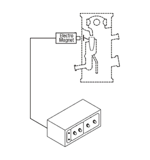
Electro-magnets are used to operate magnetically operated Reflux dividers. When 'ON' the magnet attracts the swinging funnel of the reflux divider so that distillate can be taken off.
Electro-magnets are to be mounted outside OFF the glass column, just near to the reflux divider, with the help of adjustable fittings. These are designed to use with Timers to maintain correct ratio between 'OFF and 'ON' timings of its activation.
Electro-magnets work on 220V DC power supply, for which a output socket is provided in the Timers.
| CAT. REF. | TYPE |
|---|---|
| SRPM | Non-flameproof |
Timers are designed to use with Electro-magnets to provide a correct ratio of reflux and distillate when operating a Magnetically operated reflux divider.
Two independent knobs are provided for time settings of Reflux and Off-take. During 'Off-take' it activates the electro-magnet, which attracts the swinging funnel of reflux divider, and distillation comes out. Both periods can be set accurately within a range of 0-50 seconds.
Timers work on a power supply of 230V, 50Hz.
| CAT. REF. | TYPE |
|---|---|
| SQRT | Non-flameproof |